2020년 5월 17일 일요일

Water bottle battery for bicycle lights

1. Parts:
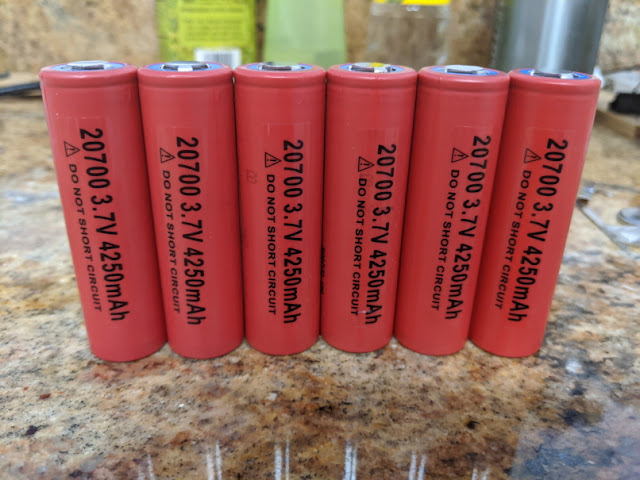
  • Sanyo 20700 x 6
  • 8A PCB and M/F Molex connectors
  • 16AWG stranded wire
  • DC extension cord

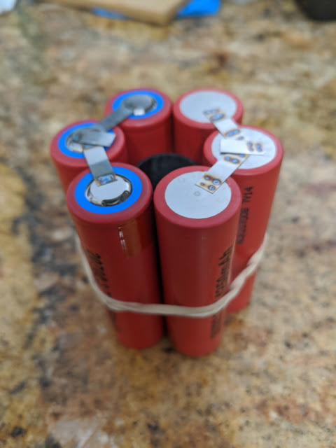
2. Weld taps on cells: for 8.4V output battery pack, three cells are bundled in parallel, and serially connected to another bundle of three parallel cells.


3. At the core, I put a 20mm carbon tube, which helps the pack maintain hexagonal shape. A PCB will be placed within the carbon.


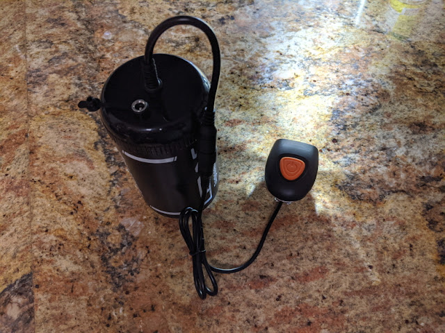
4. Lezyne container will be used for packaging.


5. Plastic sheets for insulation of the battery pack - I picked up the plastic sheet from a recycle bin.


6. Connect PCB and connectors


7. Wrapping


8. Packaging in the Lezyne container.


9. Done. Left is the finished work and the right is the original battery pack.


12750mAh, 461g


7800mAh, 336g


Charging


Final test


2020년 4월 19일 일요일

LED headlight - Radio noise filter

After installing a pair of retrofit LED headlight bulbs, I started getting noise when listening FM radio using my care stereo. The RF noise is from the driver circuits of the LED bulbs, which use high frequency switching similar to the RF radio frequency.

So I decided to design a passive filter, which I found very effective to block the noise. Now, after installing the filters, the radio noise is completely gone.


2019년 12월 15일 일요일

2s Li-ion battery (bicycle light) charger for cars

I made this for charging my bicycle light battery pack in the car.

1. A TP5100 charging module (ebay) has been used


2. Cut the cord and solder the wire on the charger module.


3. Packaging in a plastic enclosure


Because the charging indicator LED would not be seen with the case closed, I drilled a hole on the case lid and plugged a clear acrylic screw.


3. The test was successful and it charged my battery pack like a charm.


Multi-purpose variable voltage DC power supply for cars

Intended use: charging laptops and smartphones in cars, for example, at a campsite without an electricity hook-up.

Features:
USB PD 18W
QC 3.0
Low input voltage (car battery) alarm
Variable DC output


Left slot: USB PD and QC 3.0 charging ports
Middle slot: Voltage meter for the DC port on the right slot
Right slot: DC output port


For the DC output, I used a SEPIC converter module, which purchased on ebay. This converter module provides 5A output currents with 1V-30V voltage range.

To avoid over-draining the car battery, a low battery alarm module from aliexpress has also been added.

On the back, there are vent holes for cooling, power switch, and voltage adjusting knob.


LED turn signal relay MOD

1. Remove turn-signal relay from the car (TOYOTA 81980-02030)


2. The stock relay comes with a 0.03 Ohm current-sensing resistor, which detects over or under-load conditions. The most typical case for the under-load condition is that a turn signal bulb is out. Upon detection of this condition, the blinking frequency is doubled (a.k.a., hyper flash). On the other hand, when the over-load condition is detected, the blinking stops after a single blinking.


In my case, the replacement LED bulbs consumes approximately one third the power of the original Halogen bulbs. Thus, I decided to replace the current sensing resistor with a 0.1 Ohm resistor.


 3. Resistor replacement is done!


2016년 12월 31일 토요일

USB power booster with output cutoff

A single USB 2.0 port has max current limit of 0.5A. Thus, when multiple devices (some devices are power-hungry, such as a headphone amplifier) are connected via a USB hub, it can easily hit the max current limit. Fortunately, some USB hubs take external 5V input, which can make up the limited current of the source USB port.

I was one of those who were using a lot of devices, and USB hubs were essential to me (currently, more than 20 are connected to my PC via three USB hubs). One day, I touched my USB headphone amplifier by chance while the PC was powered off, and I was a bit surprised because the amplifier was so warm. That was because the device kept draining power from the external 5V input of the USB hub, even when the host PC was off. It didn't seem right to me, so when I directly connected the amplifier to my PC's USB port, not through the USB hub, no such a thing happened again.

Okay, so this is my analysis. The following table shows how the voltage sources of a conventional USB hub are routed to the output USB ports.


Ext. 5V


Connected

Disconnected

USB 5V

Connected

Ext. 5V

USB 5V

Disconnected

Ext. 5V

0V


As you can see, the external 5V input is routed to the output USB ports all the time, even when the source USB is disconnected (or the host PC is off).

However, voltage routing of a USB hub that I thought ideal was like this:


Ext. 5V


Connected

Disconnected

USB 5V

Connected

Ext. 5V

USB 5V

Disconnected

0V

0V


I spent some time trying to find out USB hubs that work as the above table. I purchased and tested at least 10 USB hubs of different brands, but unfortunately, none of them worked in the way as in the above table.

Well, now it's clear what I should do. Because there is none on the market, I should make it for myself.

Description
Output USB power is cut off when the master USB is unplugged.

- Master DC input: USB Type A
- Slave DC input: 5V DC adatper
- Output: USB Type B

Parts:
Si2323 x 1
STP80PF55 x 1
DC adapter jack
47k x 2
20k x 1
100k x 1
0.1u x 1
USB cable


Packaging


2016년 10월 9일 일요일

Rebuilding laptop batteries: Lenovo T410

1. Remove depleted batteries from the battery pack.

2. New cells: Samsung ICR18650-32A x 6

3. Desolder the original controller circuit from the original battery pack.

4. Weld anodes of two cells. Be cautious of the polarity.

5. Connect the other ends (not welded yet) of two cells with a resistor and let the cells sit until the voltage gets balanced.

6. After the cells are fully balanced, weld the other ends. Aggregate the welded cells and form a pack. Attach and solder the controller circuit.

7. Repack in the original plastic housing.