2020년 11월 7일 토요일

Toyota OEM microphone adapter for aftermarket receiver

When I upgraded the stereo of my 2013 Toyota Sienna (although I don't own the car anymore), I found that most of aftermarket receivers are not compatible with the stock hands-free microphone. So, it is usually recommended to give up the stock microphone and install a new one. However, I really wished to re-use the stock microphone and did some research myself. Actually, doing the research, I found that I was not the first who thought about re-using the OEM Mic for the aftermarket receiver. However, to my surprise, none of the precedents seemed to get successful outcomes.

The issue I identified was that, the OEM Mic system uses balanced output, which is generated by an integrated amplifier within the Mic module. On the other hand, the aftermarket Mic system uses unbalanced input. Also, since the aftermarket receiver uses a capacitor Mic, there is phantom power supply to the Mic.

The wiring diagram of Toyota stereo is shown below. We can see the two balanced output terminals MCO+ and MCO- from the Mic module.


Pin

Description

Test condition

Test value

MACC

Microphone power supply

Ignition switch off

Below 1V

Ignition switch ACC

4 to 6V

SNS2

(SGND)

Microphone connection detection

Always

Below 1V

MIN+

Microphone voice signal

-

-

MIN-

Microphone voice signal

-

-


Another issue I noticed was that the Mic module requires 5V supply, not 12V. 

Okay, so to summarize, I needed the following functionalities:

  • DC 5V supply
  • Balanced to unbalanced conversion
  • Phantom power blocking

So, I designed a converter circuit (schematic is shown below). It worked greatly for my aftermarket (Sony) receiver, so I was so happy with that.


Parts:

  • 1:1 audio transformer
    • Note: the transform ratio may need to be adjusted depending on the receivers. In my case, 1:1 transformer turned out working fine. However, for some receivers, it may saturate the AGC amp of the receiver, and distort the sound. Alternatively, a potentiometer can be connected in parallel at the output stage (Mic jack) for volume control.
  • LM7805
    • Note: if the receiver has a USB port, the 5V supply could be tapped out from the USB port (I haven't tried this though).
  • 50uF x 1
  • 10uF x 1
  • 1uF x 1
  • 50k potentiometer x 1

Schematic:

2020년 10월 18일 일요일

Reviving a 10-year old cordless vacuum. Li-ion battery upgrade. It's alive!

Parts

  • 10 x high-drain 18650 Li-ion cells
  • 5s Li-ion protection board
  • Soft start circuit
    • MOSFET (STP80NF55)
    • 2 x 100k ohm resistor
    • 4.7uF capacitor
    • 2 ohm 5W resistor
    • 1N5820

I have used a Shark cordless vacuum for 10+ years. After the first few years of intense use. it didn't hold charge any more, so I replaced the battery pack once. The original battery pack is 18v, 12 Ni-MH cells in serial. It costed around $60 or $70.

After another few years of use, I found it needs another battery replacement. But, I didn't feel to spend more money on the old machine, and just put it into the storage for a few years. Actually, while clearing up my storage room recently, I thought I would throw away the vacuum, but I changed my mind and decided to give it another life.

As I said, because I didn't want to spend too much money for the vacuum, I decided not to buy an original replacement battery pack. Instead, I decided to upgrade it to a Li-ion battery pack. However, for a high wattage device like the vacuum cleaner, I needed high-drain Li-ion cells, which usually cost over $5 per cell. Fortunately, I could find cheap Chinese high-drain Li-ion cells for $20 for 10 pack on ebay.


Build a pack: 


Soft start circuit


Pack everything in the shell 


Replaced charger with a 5s Li-ion charger - BTW, the original integrated charging circuit was bypassed, so the charging indicator LED on the handle does not work any more.


2020년 5월 17일 일요일

Water bottle battery for bicycle lights

1. Parts:
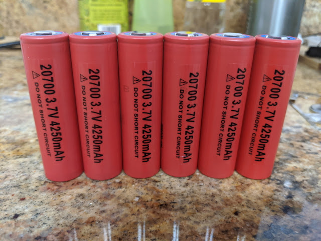
  • Sanyo 20700 x 6
  • 8A PCB and M/F Molex connectors
  • 16AWG stranded wire
  • DC extension cord

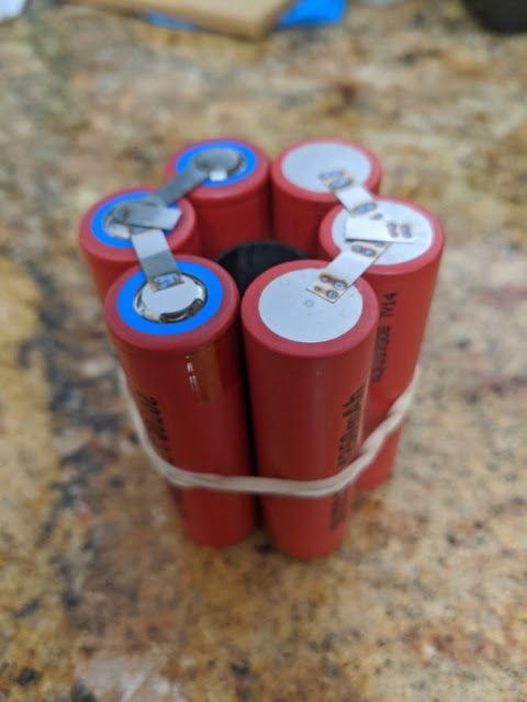
2. Weld taps on cells: for 8.4V output battery pack, three cells are bundled in parallel, and serially connected to another bundle of three parallel cells.


3. At the core, I put a 20mm carbon tube, which helps the pack maintain hexagonal shape. A PCB will be placed within the carbon.


4. Lezyne container will be used for packaging.


5. Plastic sheets for insulation of the battery pack - I picked up the plastic sheet from a recycle bin.


6. Connect PCB and connectors


7. Wrapping


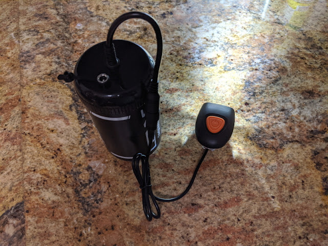
8. Packaging in the Lezyne container.


9. Done. Left is the finished work and the right is the original battery pack.


12750mAh, 461g


7800mAh, 336g


Charging


Final test


2020년 4월 19일 일요일

LED headlight - Radio noise filter

After installing a pair of retrofit LED headlight bulbs, I started getting noise when listening FM radio using my care stereo. The RF noise is from the driver circuits of the LED bulbs, which use high frequency switching similar to the RF radio frequency.

So I decided to design a passive filter, which I found very effective to block the noise. Now, after installing the filters, the radio noise is completely gone.


2019년 12월 15일 일요일

2s Li-ion battery (bicycle light) charger for cars

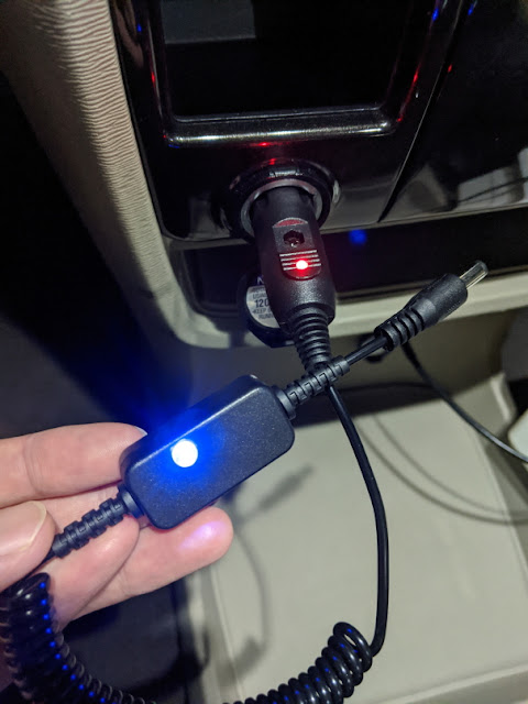
I made this for charging my bicycle light battery pack in the car.

1. A TP5100 charging module (ebay) has been used


2. Cut the cord and solder the wire on the charger module.


3. Packaging in a plastic enclosure


Because the charging indicator LED would not be seen with the case closed, I drilled a hole on the case lid and plugged a clear acrylic screw.


3. The test was successful and it charged my battery pack like a charm.


Multi-purpose variable voltage DC power supply for cars

Intended use: charging laptops and smartphones in cars, for example, at a campsite without an electricity hook-up.

Features:
USB PD 18W
QC 3.0
Low input voltage (car battery) alarm
Variable DC output


Left slot: USB PD and QC 3.0 charging ports
Middle slot: Voltage meter for the DC port on the right slot
Right slot: DC output port


For the DC output, I used a SEPIC converter module, which purchased on ebay. This converter module provides 5A output currents with 1V-30V voltage range.

To avoid over-draining the car battery, a low battery alarm module from aliexpress has also been added.

On the back, there are vent holes for cooling, power switch, and voltage adjusting knob.


LED turn signal relay MOD

1. Remove turn-signal relay from the car (TOYOTA 81980-02030)


2. The stock relay comes with a 0.03 Ohm current-sensing resistor, which detects over or under-load conditions. The most typical case for the under-load condition is that a turn signal bulb is out. Upon detection of this condition, the blinking frequency is doubled (a.k.a., hyper flash). On the other hand, when the over-load condition is detected, the blinking stops after a single blinking.


In my case, the replacement LED bulbs consumes approximately one third the power of the original Halogen bulbs. Thus, I decided to replace the current sensing resistor with a 0.1 Ohm resistor.


 3. Resistor replacement is done!